by John F. Rugh and Gary R. LaFlamme, PTR-Precision Technologies, Enfield, CT USA
As demands for higher performance migrated from aircraft engines to land based gas turbines the need for EB welding came along also. The transfer of EB welding processes from relatively thin section components in aircraft turbines to land based aero derivative turbines is straightforward since the basic design and function of both aero and aero derivative components are the same or similar. However, components of non-aero derivative land based gas turbines and steam turbines do not have the same weight restrictions of flight hardware. Therefore, much larger components with much thicker welds are encountered. The environments, performance and cost demands of land based turbomachinery are also different, which leads to different materials being used to manufacture components.
Examples of a variety of gas turbine, steam turbine and turbo compressor components that are EB welded are provided along with some of the techniques and equipment employed to EB weld them. Applications with welds as thin as 1.5 mm to over 100 mm in thickness and components from 1 kg to over 1000 kg are discussed along with material combinations used by this industry.
1. Turbine Technology Comes Full Circle
The first industrial scale gas turbine, also known as a combustion turbine, was built by Brown Boveri Company and commissioned in Neuchatel, Switzerland in 1939 [1]. Gas turbines for aerospace were developed concurrently in the 1930’s and the first turbojet powered aircraft, the Heinkel HE 178, also flew for the first time in 1939 [1].
Since the 1940’s much of the development of materials and manufacturing technology for turbines has been directed toward aircraft engines. Military aircraft engines in particular have been a driving force for turbine alloy development and the associated manufacturing technologies, including vacuum processing [2]. Aerospace requirements for lightweight structures and advanced alloys were a natural fit with EB welding when the process was commercialized in the late 1950’s and early 1960’s. The first Hamilton-Zeiss EB Welder sold in the US, installed in 1961, was used to weld aircraft engine components [3]. The materials and processes originally developed for aircraft engine use, including EB welding, have been migrating into industrial turbine usage since the late 1960’s.
2. Industrial versus Aircraft Turbines
Aerospace and land based turbines operate on the same basic principal. Some land based gas turbines known as aeroderivatives, actually share the same basic core. However, the demands of these machines can differ greatly. Large frame type turbines are designed to run for days or even months at a time operating at a steady state. This steady state is normally at either 3000 RPM for 50 Hz or 3600 RPM for 60 Hz electricity generation. These frame machines have duty cycles with have many hours, but few start and stop cycles. In contrast, operating cycles of aircraft engines go from idle speed up to maximum power for a few minutes for take-off, then back down to cruising speed for a period of minutes to hours.
Aeroderivative land based gas turbines are often used as peaking units to provide quick boosts of electrical generation capacity for short periods of time. Therefore, their operating requirements are more similar to their aircraft engine counterparts than to the large frame machines. These peaking turbines have far more start and stop cycles and fewer operating hours for a given time period than the base load frame machines.
Because of the different performance demands components with the same function can have quite different designs in aero and frame type turbines.
2.1 Combustors and Fuel Nozzles
While aircraft engine combustors are lightweight structures made from sheet metal and thin wall castings, combustors for land based industrial gas turbines can be substantial heavy weight structures. For example, the GE Frame 9 land based gas turbine incorporates 18 combustors and each combustor cover weighs more than 300 kg. By comparison, the combustor end caps for Pratt & Whitney JT8D aircraft engine, which employs a can annular type of combustor similar to the Frame 9, weigh less than 1 kg each. While the power output of the Frame 9FA (256 MW) is an order of magnitude higher than the JT8D, the weight is greater by over 2 orders of magnitude [4]. Even though the size of the aero and land based combustor components are significantly different, both are electron beam welded.
Aero and land based gas turbines generally burn different fuels. Conventional aircraft engines burn jet fuel. In contrast, natural gas is the fuel of choice for modern land based gas turbines because of its lower price and widespread availability in many parts of the world. Another important reason for using natural gas as a fuel is because it generates lower CO2 emissions than liquid fuels. Minimizing CO2 and NOX emissions along with minimizing fuel usage are important performance criteria for land based turbines.
![]()
Optimizing fuel – air mixing helps achieve these requirements. In addition to being far larger than an aircraft engine combustor, land based can annular type combustors incorporate far more complicated flow paths for fuel – air mixing, which necessitates much more welding. The air – fuel mixing process begins in the combustor cover in the GE Frame 7 and Frame 9 turbines. The mixing process in the combustor cover benefits the combustion efficiency by preheating the air – fuel mixture and it increases the longevity of the combustor cover by cooling it.
 The GTAW process was initially used to weld cover plates on Frame 7 and 9 combustor covers. When early Frame 7F and 9F covers came back from the field for overhauls, they were repaired using the EBW process. The welding results were so much better (far less distortion) than the original GTAW process that the process for manufacturing new covers was switched to EBW.
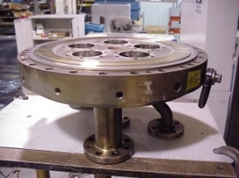
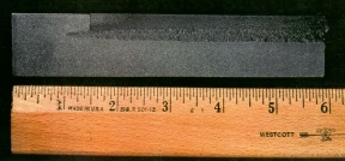
The Frame 7 combustor cover shown in Fig. 1 is 125 mm thick and 740 mm in diameter. 13 mm deep welds 2780 mm in total length are required to attach the cover plates over the gas mixing passages. An unusual feature of the EB welds in the combustor cover shown in Fig. 1 is the use of filler metal. Normally EB welds in stainless steel such as this are performed autogenously. Filler metal is used here for two reasons. First, the fatigue performance is improved and second, the use of filler allows greater machining tolerances, reducing the cost of prewelding milling operations.
The fuel nozzles themselves also rely heavily on EB welding. These assemblies consist of tube to tube welds and tube to casting welds. The materials are austenitic stainless steels and nickel base superalloys. One version of a Frame 7FA fuel nozzle has 13 EB welds per nozzle. There are 5 nozzles per combustor and 14 combustors per turbine. All this adds up to 910 EB welds required to fabricate all of the fuel nozzles of this turbine. When fully assembled, the fuel nozzles are bolted over the 5 pockets in the combustor cover shown in Fig. 1.
2.2 Vanes
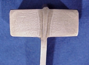
Stationary vanes, also referred to as diaphragms by some turbine manufacturers, are often inserted in the turbine as clusters of doublets and triplets. Two and three vane segments in the turbine hot section are commonly produced as investment castings. In the compressor section (cold section) some vane clusters are assembled from milled individual vanes that are EB welded together. The compressor vane segments shown in Fig. 2 are for the Siemens W501F turbine. The airfoils and gas path shroud surfaces are finish machined prior to the EB welding operation. An aircraft engine compressor vane cluster is shown just to the left of the larger land based vanes as a comparison. The airfoil section of the land based vanes is approximately 500 mm from ID to OD. The airfoil section of the aero vanes is less than 75 mm from ID to OD. Even though the size of the aero and land based components differ by orders of magnitude in size, both are EB welded.
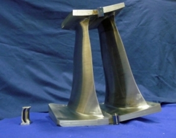 These particular vanes are milled from 410 stainless steel forgings then joined together by EB welding the inner and outer shrouds to form doublets and triplets. The faying surfaces for both the inner and outer shroud are tapered. The outer shroud of the vane shown in Fig. 2 tapers from less than 30 mm to over 75 mm in thickness. The dimensions differ slightly depending on the compressor stage. This taper requires sloping the beam current throughout the weld. Welds of this depth require run on and run off tabs to assure that the potential weld defects at the beginning and end of the weld are in areas removed from the final part.
The gas path throat area between the vanes is critical to turbine performance. Therefore, distortion from the welding process must be kept to a minimum and also kept consistent. EB welding has proven to impart small, but consistent weld shrinkage and distortion.
![]()
When prewelding dimensions take the weld distortion into account the EB welded assembly meets the tight tolerance window. A narrow, nearly parallel sided EB weld has proven to be a good choice for this joining operation for both the aero and the much larger land based gas turbine vanes.
2.3 Seals
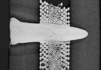 Seals are also turbine components that are similar in both aero and industrial gas turbines. Brush seals provide a barrier to interstage pressure leaks in the compressor section. They are manufactured by encapsulating the individual wire strands that constitute the brushes between retainer plates. EB welding minimizes the distortion of the assembly and the fast welding speed keeps the weld metal from migrating into the brush structure. This leaves the individual wire strands free to flex as needed to maintain a good seal as the turbine shaft moves during transient conditions.
Some of the steel alloys in the brush assembly are prone to cracking during the welding process. To prevent this potential problem the electron beam can be used to preheat assemblies prior to welding. New EB welding systems even allow the preheating to be performed simultaneously with the welding.
2.4 Cases
 Since aero derivative turbines normally share a common core with their aero counterparts, the cases are fairly similar in geometry. To save weight the case materials can be different between the flight and land based turbines. In the cold section titanium is often used for aero turbines to save weight. Less expensive stainless steel alloys are normally used for land based applications where weight is not an issue. Another major difference between the aero and aeroderivative versions is the thickness of the components.
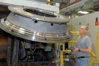
The weld in the aeroderivative turbine case shown in Fig. 4 is 40 mm deep. The material is IN 718, a common case material that is also used in aircraft turbines. The primary difference is the thickness of the case. Equivalent aero cases are less than one third the thicknesses of their land based counterparts.
3 Steam Turbines
Industrial turbines have been in use far longer than gas turbines. Hydro turbines have been used since antiquity. Steam turbines used to generate electricity and drive industrial machinery have been manufactured since the late nineteenth century. The first modern steam turbine was patented in 1884 by Parsons [5]. By 1900 steam turbines had progressed to producing electricity on a commercial scale as evidenced by the installation of the first public utility steam turbine generator at the Hartford Electric Company, Hartford, CT USA [6].
3.1 Diaphragms
 The use of EB welding to manufacture steam turbine components trailed its use in manufacturing gas turbine components. It wasn’t until the late 1960’s that EB welding was used to weld steam turbine diaphragms. By 1985 an EB welding system capable of diaphragms 3 m in diameter weighing up to 10 tons had been installed in the US. This 60 KW system was capable of producing single sided welds up to 150 mm in depth [7].
![]()
Even though the EBW process has been used for decades for fabricating steam turbine diaphragms, recent advances in high voltage power supplies and high speed beam deflection have made the process easier. Two potential problems encountered when EB welding these components are magnetism and the cleanliness of the steel. Performing high power welding on plain carbon steels inside a vacuum chamber releases entrapped gases in the material. This caused “arc-out” problems with older transformer type high voltage power supplies. Newer switch mode type power supplies are able to rapidly drop the voltage, quench the arc and keep welding, which has made it much easier to weld non-vacuum refined materials.
Magnetism can be problematic during the EB welding process because magnetic fields deflect the beam and can cause the beam to miss the weld joint. Steam turbine diaphragms are fabricated from materials that are dissimilar and magnetic. High Cr steels, such as 410 stainless steel, are commonly used for the steam path walls and airfoils. Plain carbon steel is used as a backing material. Both materials can harbor residual magnetism prior to welding. This type of magnetism can usually be rendered harmless to the welding process by demagnetizing components prior to EB welding.
Dealing with this plain carbon to high chrome steel dissimilar material couple is more difficult. During EB welding a magnetic field inside the part is created by the thermoelectric effect [8]. Welds under 25 mm in depth in plain carbon steel to 12 Cr steel joints have proven to be weldable with minimal problems. Deeper welds require adjustments to the process. Using a wider weld can help avoid missed joints at the root of deeper welds joints caused by beam deflection. Angling the beam to counteract the pull of the magnetic field can also help keep the beam on the joint. The most promising technique is using fast beam deflection to produce two simultaneous keyholes. Earlier work shows that the magnetic fields produced by two closely spaced keyholes may counteract one another and eliminate the beam deflection [8]. Some of the newest EB Welding systems incorporate this deflection capability.
4 Turbo Compressors
Turbocompressors can have either axial flow or radial flow. Both aero and land based gas turbines incorporate a turbocompressor to compress the incoming air prior to it being mixed with the fuel and injected into the combustion chamber or chambers. However, not all turbocompressors are part of a gas turbine. Large industrial sized radial flow turbocompressors, otherwise known as centrifugal compressors, are used for pipeline gas transmission, liquefying natural gas, processing petrochemicals and to reinject gas to counteract the pressures encountered drilling oil & gas wells. Dresser-Rand, one of the largest manufacturers of compressors for the petrochemical, oil and gas industries, uses EB welding to manufacture their shrouded impellers. D-R’s multistage centrifugal compressors range from less than 0.5 m to over 4 m in diameter and up to 6.5 m in length [10].
4.1 Impellers
 Impellers are the components in turbocompressors that perform the compression work and their conformance to tight tolerance designs greatly affects their performance. Since the 1990’s D-R has used EB welding to fabricate shrouded impellers partly because the low, predictable weld distortion allows the parts to be fabricated within intended design tolerances.
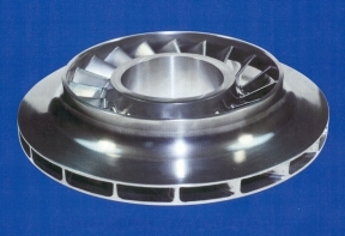
These two piece impellers are made by milling blades into forged disks to form integrally bladed wheels. Covers are milled to mate with the tips of the blades. The two are joined by a unique process that combines EB welding and brazing called EBrazeTM. The joint is made by preplacing braze foil along the tops of the impeller blades, placing the cover on and then EB welding through the cover with a blind T-weld as shown in Fig. 6.
The cover shown in Fig. 6 is 12.5 mm thick. The blade is only 3.2 mm thick so the position and angle of this weld is extremely critical. This weld consumes 60% of the blade to cover interface and the heat from the weld melts the braze foil to join the remaining interface area. The braze material also forms a small fillet at the edge of the blade to cover interface which acts to eliminate a potential stress riser. Completely sealing this interface eliminates a small crevice that could enable stress corrosion cracks when the impeller is in service. This is an important consideration since the gases being compressed can be corrosive.
 The 3D impeller shown in Fig. 7 is fabricated by joining a 5-axis milled base to a milled cover; a process that would is made possible by CNC contouring of 5 mechanical exes and 4 additional beam parameters. The blades are inclined at the ID and are perpendicular to the base and cover at the OD. The cover thickness also varies from the ID to the OD. To perform this blind T-weld the beam must follow the center axis of each blade. The beam intersects the cover at an acute angle at the ID and finishes normal to the surface at the OD.
![]()
A directional beam deflection pattern is used to tailor the width of the weld so that the width of the weld at the interface remains at a constant distance from the edge of the blade on both sides. The size of the deflection pattern and the beam power also slope continuously throughout the weld while the 5-axis motion system follows the center axis of each blade.
5 Summary
Starting with aircraft engines and then migrating to land based gas turbines, steam turbines and more recently industrial turbocompressors, electron beam welding has been an important tool for turbomachinery manufacturers. At times, new turbomachinery designs have driven the development of new EB welder capabilities and at other times new EB welder features have allowed improved turbomachinery to be realized. It has been a beneficial symbiotic relationship for over 50 years.
6 Literature
[1] MIT Gas Turbine Laboratory [Internet]. Cambridge (MA): Early Gas Turbine History. [Cited 2012 Jan 15]. Available from: http://web.mit.edu/aeroastro/labs/gtl/early_GT_history.html
[2] Sims, C. T., Stoloff, N. S., Hagel, W. C. editors. Superalloys II, New York, NY: John Wiley & Sons (1987). pp. 5-9.
[4] Kitchin, R. A.: Aerospace Production Applications for Electron Beam Welding. Proceedings of the Electron Beam Welding Symposium, November 7 and 8, 1966. Department of Welding Engineering, The Ohio State University, Columbus, Ohio, USA. (1966). pp 73-85.
[4] Turbomachinery International: Handbook 2012 (2011), 52(6), pp 89.
[5] Parsons, C. A.: The Steam Turbine, The Rede Lecture. Cambridge University Press (1911).
[6] Westinghouse Electric Company [Internet]: Company History Timeline. [Cited 2012 Jan 15]
2012 Westinghouse Electric Company.
Available from: http://www.westinghousenuclear.com/our_company/history/timeline/1900_1939.shtm
[7] Fritz, D.: Heavy Section EB-Welding. I.I.W. Doc. No. IV-453-88 (1988)
[8] Blakeley, P. J. and Sanderson, A.: The Origin and Effects of Magnetic Fields in Electron Beam Welding. Welding Journal (1984), 63(1), pp. 42-49.
[9] LaFlamme, G. and Rugh, J., PTR-Precision Technologies, Inc. and MacWilliams, S. and Hendryx, R., Dresser-Rand Company: New EB Welder Features Developed to Manufacture Five-Axis Impellers. Welding Journal (2006), January 2006, 85(1), pp 44-47
Page 5