Abstract
This paper provides a technical overview of the unique features of the electron beam welding process including several applications. Weld cross sections of production parts will be shown to demonstrate obtainable weld shapes. Solutions to specific weld challenges using the EB process will be shown. In addition, an overview of today’s welding equipment and a brief look at future developments will be presented.
Introduction
The electron beam (eb) welding process is used in a variety of industries. Applications range from fully automated, high productivity and low cost automotive in-line part production to single part batch processes in the high-cost aircraft engine industry at the other end of the industrial spectrum. For those manufacturers and many others not specifically mentioned here, welding processes have to meet increasingly stringent standards that have become more prevalent over the years. In this regard, the eb welding process is well-positioned to provide industries with the highest quality welds and machine designs that have proven to be adaptable to specific welding tasks and production environments.
What is an Electron Beam?
In an electron beam welder electrons are “boiled off” as current passes through a filament which is in a vacuum enclosure. An electrostatic field, generated by a negatively charged filament and bias cup and a positively charged anode, accelerates the electrons to about 50% to 80% of the speed of light and shapes them into a beam. Due to the physical nature of the electrons – charged particles with an extremely low mass – their direction of travel can easily be influenced by electromagnetic fields. Electron beam welders use this characteristic to electromagnetically focus and very precisely deflect the beam at speeds up to 10 kHz. Recent machine developments make it possible even to go up to 200 kHz. With today’s CNC controls, the beam focus as well as the beam deflection are part of the weld schedule and can be variably programmed along with other process parameters.
How does the Process Work?
When fast moving electrons hit a metal surface they are decelerated which transforms the kinetic energy of each individual electron in the beam into thermal energy in the component. This transformation is stable in the high 90% range for all metals regardless of whether the electrons hit the surface at a perpendicular or shallow angle. As a practical matter, this physical behavior makes the process very robust and reliable!
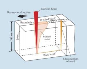
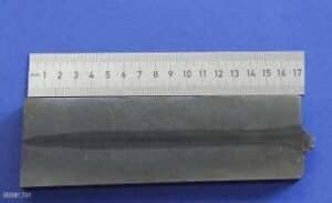
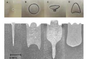
When electrons in a focused beam hit a metal surface, the high energy density instantly vaporizes the material, generating a so-called key hole (Figure 1). A characteristic of this phenomenon is that it allows the unique capability for deep, narrow welds with very small heat affected zones (HAZ) and minimized thermal distortions of welded assemblies (Figure 2). Depth-to-width ratios of up to 40:1 have been achieved in production for many years.
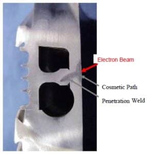
Special circumstances may require conduction mode welding (as opposed to key-hole welding) that typically produces wide and shallow welds. Conduction type welds can be used e.g. for cosmetic paths to smoothen the top bead of key hole welds in a subsequent operation (Figure 3). How is this done? By lowering the beam power and either defocusing the beam and/or widening the beam by using deflection pattern.
Pattern Generator – A Unique Welding Parameter
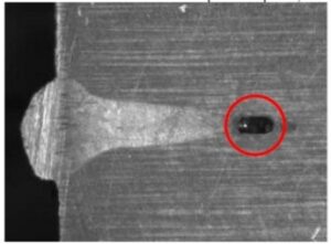
Narrow and deep welds are typically more subject to porosity, most often at the root but also in the middle of the weld. To explain the mechanism for the creation of porosity we have to look into the key hole and see what is going on there. Let’s start with the basics – the key hole. As the name implies, it is a hole with a high vapor pressure in the middle that presses the molten material firmly against the side walls. As the electron beam is moved forward, material melts at the front of the beam. This melt moves very dynamically to the back of the beam and rapidly solidifies in this position. This combination of dynamic movement and fast solidification may result in vapor pockets created by a too rapid solidification of the molten material behind the beam. These entrapped pockets show up as porosity in cross weld sections (Figure 4).
The questions arises at this point, how can we prevent vapor pockets? One of the parameters provided by the eb process is the capability to change dynamic movement of the molten material by influencing the size of the key hole. This parameter, unique to the eb process, deflects the beam at a rate of a few hundred Hertz in a pattern, such as circle or arrow head (Figure 5). The size of the hole diameter can be enlarged which results in more time for metal vapor to escape and, in turn, prevents the creation of vapor pockets. All values of this unique deflection parameter, such as frequency, pattern direction and size in x- and y-direction, can be programmed. Adjustments to these values can significantly enhance the stability of key holes in most welding applications.
Welding of low melting alloys, like aluminum or magnesium, may initially be a challenge as the high beam power concentration easily can overheat the material possibly resulting in porosity in the weld, rough top beads and splatters. Again, dynamically deflecting the beam in a pattern at a few hundred Hertz and adjusting the other deflection values helps decrease the power density in the focus spot and thereby prevents overheating of the alloy. Porosity can be minimized or avoided completely, the top bead can be smoothened and the creation of spatters can be avoided in most circumstances.
Although it is possible to produce very narrow welds, it is not always desirable since the combination of part and tooling tolerances may be too large for a narrow weld. The beam may not always hit the joint exactly where it should and thereby increases the risk of losing penetration or even entirely missing the joint. In these situations it is advantageous to be able to adjust the weld profile, very often the width at a given penetration, in order to find the right balance between reliable beam-to-joint repeatability in mass production and the lowest possible heat input for a minimum level of part distortion. Again, the pattern generator is the perfect tool to balance these different technical requirements by allowing continuous adjustments to be made to the width of the weld with almost parallel sides.
In addition to eliminating the aforementioned porosity, the use of the pattern generator can also improve the cosmetic appearance of the top bead in a secondary operation after the penetration weld.
Further improvements to weld quality can be achieved by using different weld patterns to eliminate undercuts and irregular penetrations. The latter also benefits from a higher frequency beam pattern deflection that, to a large degree, reduces the spiking at the root of a weld.
What Materials can be Welded with the EB?
Virtually all metals can be welded with an electron beam. Of course, the quality of welds depends on the metallurgy as well as other technical criteria, such as welding parameters and joint design. Filler material is not typically used to join the majority of components hence the metallurgy does not change. This makes the electron beam welding process simple and more cost effective. As with any rule, there are exceptions. There are materials where it is advantageous to use filler metals, e.g. avoiding weld cracking in 6000 series aluminum. The use of 4000 series aluminum filler wire changes the metallurgy and prevents cracking. It is beyond the scope of this paper to detail the weldability of various metals; therefore, the following examples will focus on certain production applications.
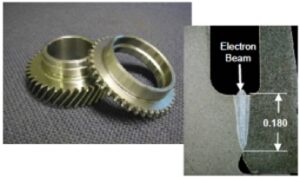
Low to medium carbon micro-alloyed steels are typically used for manual transmission gear components in the automotive industry (Figure 6). Some of these materials are more prone to develop cracks after welding due to the significant hardness increases in the HAZ. These are caused by the quenching effect after welding and can be influenced by the width of the weld and the welding speed. Preheating the components is a common remedy used to substantially reduce hardness increases. It has become common practice in the automotive industry to preheat gears prior to welding in order to reduce the quenching effect in the HAZ. A welcome side effect of preheating in mass production is that welding speeds can be safely increased, making the process more economical.
Welding of automatic transmission components is yet another application used by the automotive industry. The range of components to be welded typically includes a variety of designs for shaft assemblies as well as planet carriers. The materials range from low carbon sheet metal for clutch carriers to medium carbon, micro alloyed steels for shafts. The molten low and medium carbon materials mix together without posing any problems.
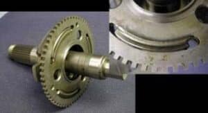
Light and medium duty planet carriers are made of low carbon steel sheet metal. This material is perfectly weldable; the challenge lies in the design of these parts which have 3 to 5 segments that need to be joined. The specification of these segmented welds typically does not allow for substantial underfill of material either at the beginning or at the end of the joint (Figure 7).
The combination of deflection pattern and continuous adjustment of the beam power helps to mitigate this underfill thereby optimizing the joint quality to meet the specification. Advanced designs of heavy duty planet carriers are forged of micro alloyed steels containing about 1% Manganese and 0.2% carbon. A challenge greater than the sheet metal design is posed by joint segments with varying thicknesses that require a change of power not only at the beginning and the end of the joint but also in between. Again, a deflection pattern in combination with a continuous adjustment to beam power permits the development of a robust set of welding parameters that hold up in daily production on the manufacturing floor.
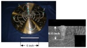
The use of stainless steel is very common in the industry because of its corrosion resistance to many substances, gas or liquid, which contact its surface. Most grades of stainless steels can be easily welded with the electron beam and most importantly, the welds are corrosion resistant as the parent material. As an example, plates with complicated cooling channels for the processing industry require weld penetrations of up to 0.150 inches. The 2-dimensional weld pattern shown in Figure 8, has total weld length of up to 300 inches which introduces a high amount of heat into the plate. Narrow welds for a limited heat input minimize and keep the amount of distortion at a technically acceptable level and are therefore critical to this application.
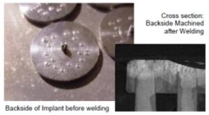
Titanium alloys are widely used in the aircraft industry for their high strength-to-weight ratio and their corrosion resistance. The electron beam welding process is widely used in this industry to join new and to repair used components. Other fields of applications for Titanium materials are, for example, medical implants for which pure titanium is preferred over its alloys. The pins of the implant, shown in Figure 9, need to be welded into the base plate. The electron beam hits the pins from the flat back of the plate which gets machined after the welding. For these small pin diameters it is advantageous to deflect and move the beam in circles electronically rather than mechanically. The welds are staggered to equalize the heat distribution in the base plate. Critical to this application is a partial, constant weld penetration to prevent a breakthrough of the beam and keep the front of the implant absolutely vapor and splatter free.
What types of Electron Beam Welders are being used?
Manufacturing cost and quality are key goals to consider in the fabrication of components. Each industry applies its own criteria to reach these goals. From a machine tool vendor’s point of view these goals translate into different machine designs, such as welders for low to medium production or welders for mass production with short cycle times.
The indexing table welder design was established as a reliable machine tool for high-volume production of assemblies several decades ago. This type of welder typically employs a 2-station dial index with one part in each of the stations.
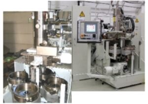
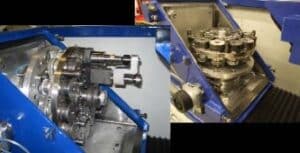
To further optimize productivity, the number of stations can be increased to 3 or 4 and the number of assemblies in each station may be also increased, depending on their size (Figure 10). A further reduction in cycle times to this production machine has been achieved through a design change that integrates a load lock chamber in front of the vacuum processing chamber (Figure 11). The absolute shortest cycle times can be achieved with the so-called nonvacuum electron beam welder which welds parts in atmospheric pressure. This technology produces welds that are wider than those produced in a vacuum.
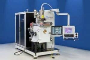
Medium volume production is typically performed in chamber machines with specialized tooling. Since the majority of applications need axial or circumferential welds, multiple part holders should be used whenever possible in order to make the process more cost effective. Several different machine designs have been manufactured for the industry over the years, the simplest of which employs a vacuum chamber with a door in the front (Figure 12). A more advanced design incorporates a drawer style chamber which allows the tooling including parts to be entirely removed from the chamber for easier loading and unloading of assemblies and tooling changes (Figure 13).
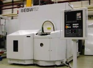
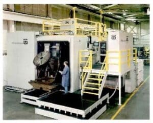
The most flexible welders in terms of welding assemblies of all sizes and shapes are the so-called chamber welders with CNC-controlled x-/y-tables. These welders come in all sizes with vacuum chamber volumes ranging from about 1 m3 to more than 100 m3. Axial and circumferential welds can be performed with a rotary tilt device that is mounted on top of the x-/y-table. The electron beam gun is located either inside the vacuum chamber or stationary on the outside (Figure 14).
One commonality of these electron beam welders is that all beam parameters and all mechanical axes are numerically controlled either by a PLC or a CNC. As with any modern machine tool, all process parameters can be stored by their respective part numbers and retrieved at a later date. In today’s eb welders a machine program constantly monitors the actual values of all electrical parameters and compares them to the set values. If an actual value exceeds the programmed tolerance of the set value, the machine will either stop or notify the operator of this fact.
This machine control can be considered the most basic quality control system; of course, the numeric control offers network connections for more elaborate quality control functions and data acquisition.
EB welding technology has reached new heights, but development is still ongoing. It centers on improvements to the electromagnetic focus and deflection system to shorten their response times. Today, fast beam deflection systems allow for electronic imaging of the assembly around the joint area or splitting of the electron beam to weld 3 or 4 spots virtually at the same time. Ongoing developments seek to combine various processes, such as welding with 3 beams while simultaneously preheating the joint area in front of the weld pools with 3 additional beams.
Summary
Electron beam technology had advanced for decades reaching its current highest level. EB welders have matured to meet the demands of modern industries such as the low volume, high quality aircraft industry, as well as mass production-orientated automotive industry. Different types of electron beam welders have evolved over the years influenced by the market to address specific needs from both a technical and economical perspective. In all these applications the process proved to be robust and flexible at the same time.
All grades of steel can be welded, as well as low melting alloys such as aluminum and magnesium, and high melting materials such as Nickel- and Cobalt-based alloys. The pattern generator, unique to the eb welding process, has proven to be very powerful in stabilizing the key hole to improve the process’ robustness and produce defect-free welds.